Physical Computing: Final
December 09, 2020
Pixel Topographies
The Concept
My family sold the house I grew up in this year, which was very sudden, but for the best. I had never really been that connected to my home state, but when I realized I may never go back there, I realized that I had come to really appreciate it as a place to grow up.
We ended up renting a house not too far from where I grew up to get through the pandemic, but it made me think about what it was that caused me to become so nostalgic. What kept popping into my head was that it is a beautiful place. It has lovely forests, beautiful colors, coastal towns, and even a few mountains.
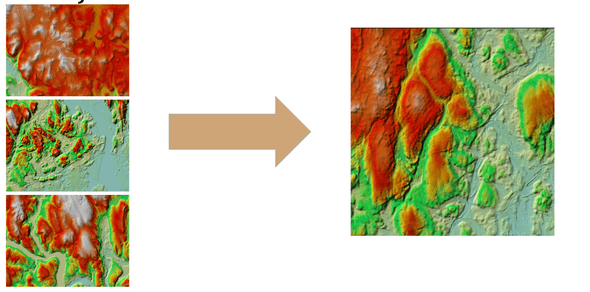
Then, I stumbled across this site, which shows the elevation in CT using colors.
I’ve also been inspired by the idea of a computer screens being 3-Dimensional. Some of Refik Anadol’s work reflects this. They have beautiful edges and ridges, but entirely 2D and on screens. I wanted to ask the question, can we make a screen in real life?
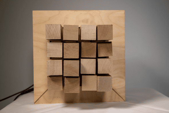
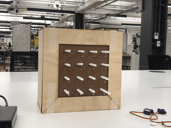
For this assignment, I have decided to combine these concepts to create “Pixel Topographies”, a 3D pixel computing piece that visualizes CT elevations
The Product
The How
Machine Learning
For this project, in order to facilitate a diverse and unique set of data values, I used RunwayML to generate a GAN Model that will create random elevation maps based on real data.
I used the website listed above to grab about 250 images of CT elevations. Usually this is a very small dataset, but since the data is clear, high quality, and very similar, the output would work great.
I brought this data into RunwayML and trained it over a couple of hours. As I suspected, the output turned out phenomenally.
P5.js
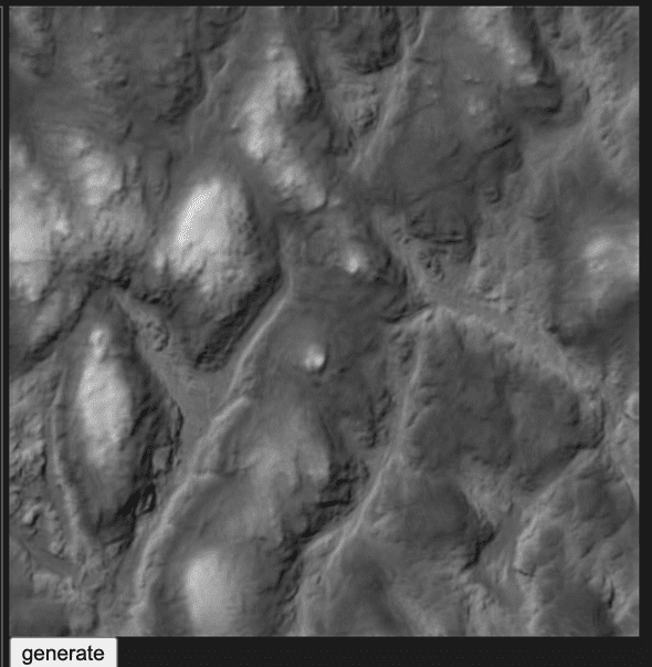
From here, I used a “hosted model” in runway to access the model and bring new images into p5.js.
After that, I used the pixel array and get(); function to grab the upper left color of each pixel (according to a resolution variable).
Unfortunately, it is really hard to bring an RGB value to a single byte, and using HSB Hue can’t work here because of how the colors are mapped to the elevations. So, I tried black and white. To my surprise, it preserved the topography of the image.
But, playing with black and white can be complicated in that you have to decide how you achieve the grey color. My first instinct was to average RGB, but that allowed for VERY little variance in colors. So, I used the Green value of the RGB
Then, those values populate into a 2D array, which I write 1 by 1 to the arduino.
Arduino
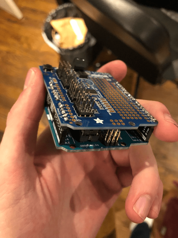
First, I needed to find a way to control 16 motors at once. This did not end up being very difficult, because Adafruit sells a 16 motor pwm shield for arduino Uno. So, I soldered the pins into it and connected it to the board.
Using the Adafruit servo library, I was able to grab all of the values from the serial port and write those values to my project. Frankly, it wasn’t that hard.
In the next iteration of this project, I want to make sure that the servos go slowly instead of immediately.
Code:
#include <Wire.h>
#include <Adafruit_PWMServoDriver.h>

// called this way, it uses the default address 0x40
Adafruit_PWMServoDriver pwm = Adafruit_PWMServoDriver();
// Depending on your servo make, the pulse width min and max may vary, you
// want these to be as small/large as possible without hitting the hard stop
// for max range. You'll have to tweak them as necessary to match the servos you
// have!
#define SERVOMIN  120 // This is the 'minimum' pulse length count (out of 4096)
#define SERVOMAX  480 // This is the 'maximum' pulse length count (out of 4096)
#define USMIN  600 // This is the rounded 'minimum' microsecond length based on the minimum pulse of 150
#define USMAX  2400 // This is the rounded 'maximum' microsecond length based on the maximum pulse of 600
#define SERVO_FREQ 50 // Analog servos run at ~50 Hz updates

// our servo # counter
uint8_t servonum = 0;

int incomingAngle;
int nums[16];
int matrix[4][4];

long lastData = 0;

void setup() {
  Serial.begin(9600);
  Serial.println("8 channel Servo test!");

  pwm.begin();
  pwm.setOscillatorFrequency(27000000);
  pwm.setPWMFreq(SERVO_FREQ);  // Analog servos run at ~50 Hz updates

  for (int i = 0; i < 16; i++) {
    pwm.setPWM(i, 0, SERVOMAX);
    //pwm.setPWM(i, 0, 100);
  }
  delay(1000);
  getNewData();
}

void loop() {
  int servonum = 0;
  for (int y = 0; y < 4; y++) {
    for (int x = 0; x < 4; x++) {
      int newVal = matrix[y][x];
      pwm.setPWM(servonum, 0, newVal);
      servonum++;
    }
  }
  if (servonum >= 16) {
    servonum = 0;
  }

  if (millis() - lastData > 1000) {
    lastData = millis();
    getNewData();
  }
}


void getNewData() {
  int count = 0;
  if (Serial.available() > 0) {
    for (int i = 0; i < 16; i++) {
      int fromSerial = Serial.parseInt(); //random(SERVOMIN, SERVOMAX);
      fromSerial = map(fromSerial, 0, 179, SERVOMIN, SERVOMAX);
      nums[i] = fromSerial;
    }
    for (int y = 0; y < 4; y++) {
      for (int x = 0; x < 4; x++) {
        matrix[y][x] = nums[count];
        Serial.println(matrix[y][x]);
        count++;
      }
    }
  }
}
Linear Actuation
So now that the code is covered, I want to show how I made the motors work.
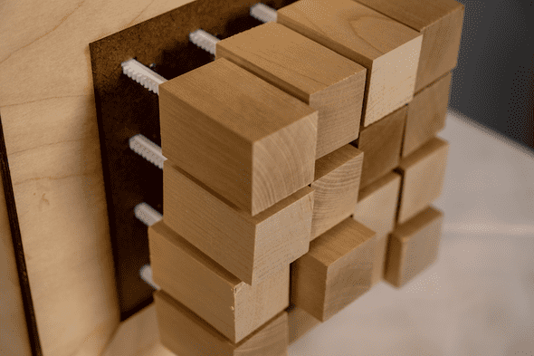
The pixels had to move in and out. To do this, I needed to create a grid of linear actuators. Unfortunately, linear actuators are very expensive.
So, I was able to use these designs to make everything work.
Using a 3D printer, a little bit of editing the gears in Maya, and some 2 part epoxy, I made a linear actuator
Fabrication
Here, I have decided to dump a chronological process of my fabrication.
Written by Philip Cadoux, current ITP student and Creative Technologist. Follow me on Instagram
