Physical Computing: Week 02
September 22, 2020
Lab 1: Digital Input and Output with an Arduino
Much of the beginning of this lab was reading and setting up the following:
Add Digital Outputs
This is the first time I am adding digital outputs to a circuit via Arduino. I was able to successfully set up the circuit, but immediately got an error in the code.
This was a very simple error, where I used ’=’ instead of ’==’, but I was very unfamiliar with the error outputs on Arduino. Turns out it is very intuitive and I looked like an idiot sending this very clear error to my class and being like “help me”
Nonetheless, the code worked great with 2 lights:
void setup() {
  pinMode(2, INPUT);
  pinMode(3, OUTPUT);
  pinMode(4, OUTPUT);
}
void loop() {
   // read the pushbutton input:
   if (digitalRead(2) == HIGH) {
     // if the pushbutton is closed, one on, one off:
     digitalWrite(3, HIGH);
     digitalWrite(4, LOW);
   }
   else {
     // if the switch is open, other on, first off:
     digitalWrite(3, LOW);
     digitalWrite(4, HIGH);
   }
 }
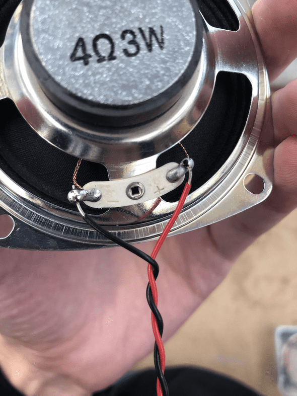
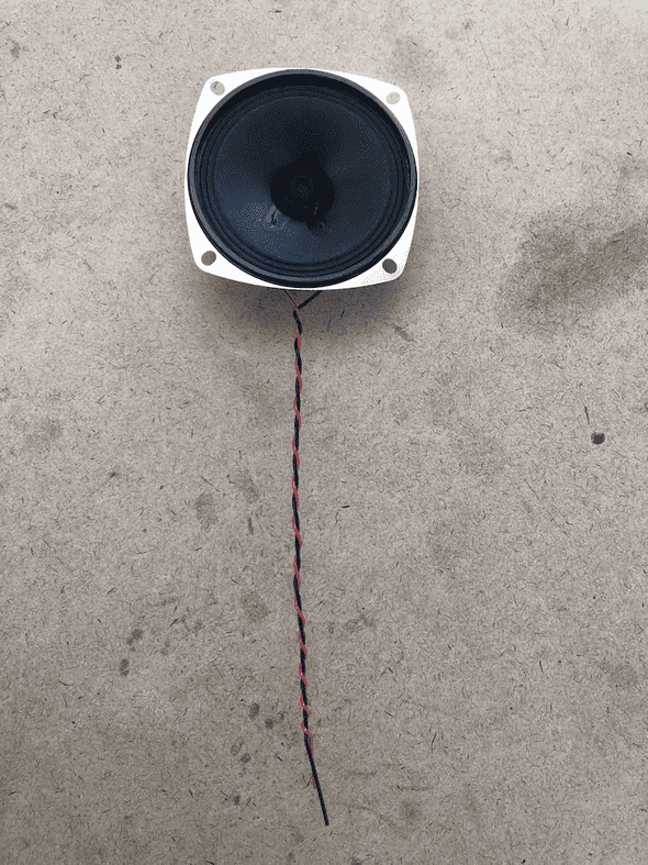
For this lab, I did not wire up the speaker. I needed to solder and wanted someone to show me (Shout out to Viola from Tom Igoe’s class who helped me on the floor, after I watched the video).
Lab 2: Analog In with an Arduino
Working with a Potentiometer
I had no issues with this lab, the code worked as intended, so I will not include it here.
That said, this is the first time I soldered!
I then hooked up that component to the Arduino.
Code for speaker:
const int pinNumber = 9;
int analogValue = 0;
int frequency = 0;

void setup() {
  // put your setup code here, to run once:
  Serial.begin(9600);
  pinMode(pinNumber, OUTPUT);
}

void loop() {
  // put your main code here, to run repeatedly:
  analogValue = analogRead(A0);
  frequency = (analogValue /4);
  analogWrite(pinNumber, frequency);
  Serial.println(frequency);
}
Phototransistor Variable Resistor
I was not able to get the LED to light very much (it was very very faint). I think, now that I have finished the lab, I may need to map the range to higher values? That might work. Still, I was able to read variable resistance on the phototransistor.
Finding your sensor range
This video was taken before I set the mapping up. The video I took with map, doesn’t show the Serial Monitor, unfortunately, but the code is below.
When looking for my range, I found that it was close to the example, so for simplicity I used that. My code is probably just a smidge different than this code, because I tried to get the 2 FSRs to work before the code example to make sure I understood it.
const int ledPin = 9;
const int ledPin2 = 10;
int analogValue = 0;
int analogValue2 = 1;
//int brightness = 0;
//int brightness2 = 0;

void setup() {
  // put your setup code here, to run once:
  //Initialize serial communications at 9600 bps:
  Serial.begin(9600);
  //declar the led pin as an output
  pinMode(ledPin, OUTPUT);
  pinMode(ledPin2, OUTPUT);

}

void loop() {
  // put your main code here, to run repeatedly:
  analogValue = analogRead(A0);
  int brightness = map(ledPin, 400, 900, 0, 255);
  analogWrite(ledPin, brightness);
  Serial.println(ledPin);

  analogValue2 = analogRead(A1);
  brightness = map(ledPin2, 400, 900, 0, 255);
  analogWrite(ledPin2, brightness);
  Serial.println(ledPin2);
}
Written by Philip Cadoux, current ITP student and Creative Technologist. Follow me on Instagram


