Physical Computing: Week 03
September 25, 2020
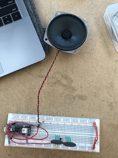
Lab 1: Tone Output Using An Arduino
I started by quizzing myself on how to read and re-produce schematic drawings for circuits. I mostly got the first one right, but screwed up a little bit when putting the A0 pin between the resistors.
Next, I took a reading for the sensor range. The force resistors I used gave me an approximate range of 0 - 1023.
Mapping that to 100 - 1000 gave me a nice, low, frequency that was clear. I also removed the 100Ohm resistor to see how much louder it would get (not much, but I did notice).
Next, I worked on making the pitches.h file and adding in the code from the pitch. The code as provided worked well and I was able to get it to play once. For the sake of documentation, I moved the for loop to the loop() function, which allowed me to play it over and over again. I also added a 1000ms delay after the loop, so that there was distance between the melody plays.
void loop() {
  for (int thisNote = 0; thisNote < 8; thisNote++){
    //take one second and divide by the note time (for example, 100 / 4, 1000/8)
    int noteDuration = 1000/noteDurations[thisNote];
    tone(8, melody[thisNote],noteDuration);

    //pause for the not's duration+30 ms
    delay(noteDuration +30);
   }
   delay(1000);
}
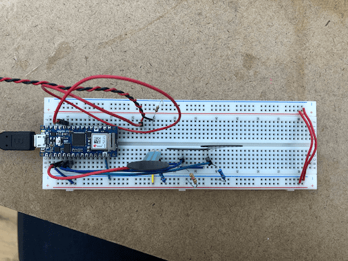
Again, I tried to make the circuit without the use of the nano imagery. I totally thought I had it right, but the sound simply would not play. Turns out, I had the Analog inputs in-line with the power, when it needed to be with ground.
I was able to discover this by using Serial.println, which was always returning the highest range of my sensor. After trying a few things, I re-referenced the circuit and learned I was wrong.
I then wrote the code almost the same, and was able to get it to work! Unfortunately, C3 was too low to actually hear, so I chose notes much higher, so I can hear them. I also upped the threshold because 10 was giving me beeps and such sometimes. I also swapped out the force sensor for a button, which also worked (of course).
LAB 2:
Once again, I tried to make the circuit only using the schematic. FINALLY, I got it right.
I found my sensor range to be 0-900. The code worked as intended and I was able to move the servo without issue!
Written by Philip Cadoux, current ITP student and Creative Technologist. Follow me on Instagram

