Energy: Solar Project
April 06, 2021
Solar Project:
Concept
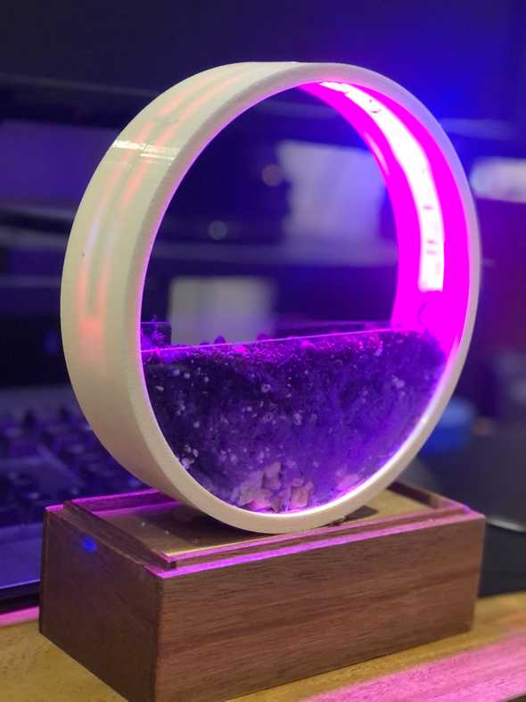
A solar reflective grow light, aimed at those who live in low-light environments
As New Yorkers, we can often expect to either know or be someone who lives in an environment painfully void of windows. Dark and dinky apartments is the norm and having a place with large, bright windows, costs a lot of money. But, that is often the reality of this city, unfortunately. So how can we make these spaces as habitable as possible?
On top of living in a dark environment, NYC is also a pressure cooker with lots of stressors and work on the daily. People often turn to hobbies and simple things that can generate positive emotions. Now, especially with the pandemic, people have taken to raising plants in their free time. Sadly, some plants require a lot of light to thrive. Because of this, humans have created “grow lights” which are strips of LEDs (though they don’t have to be) that emit the light frequencies that facilitate photosynthesis.
Often, the full spectrum of light provided by the sun is not necessary for photosynthesis. There exists a range of frequencies called the PAR (Photsynthetically Active Radiation), which are between 400-700nm (Red, Blue, Green, where green is the least important). Grow lights replicate this perfectly, bringing ideal environments with constant uptime.
However, people usually have to set timers and etc to make sure these turn off after a certain amount of time. What if we could rely on the phases of the sun to keep time for us?
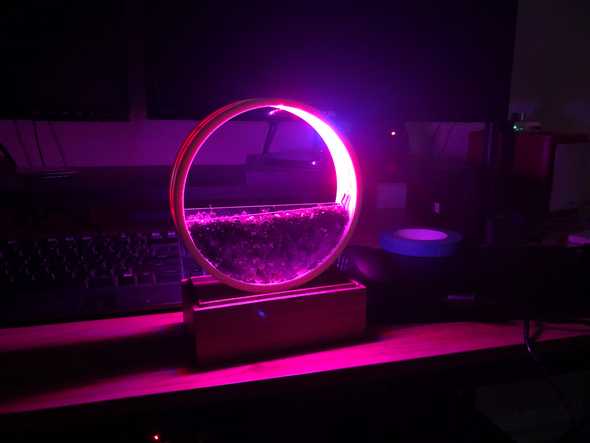
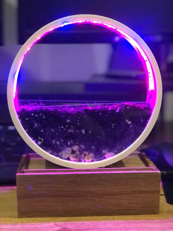
This project takes advantage of just 1 window to help replicate natural light. A solar-powered, suction-mounted arduino is attached to whatever window is available. This not only transmits light data to another device, but has near 100% uptime from the solar panel (running up to two or three days without sunlight on a full charge). Then, a cleanly designed planter with grow lights attached will dim and brighten according to those light levels.
The version I have created here today is a prototype. It isn’t properly water proofed, and more research needs to go into fine tuning the light readings and build order.
Circuit
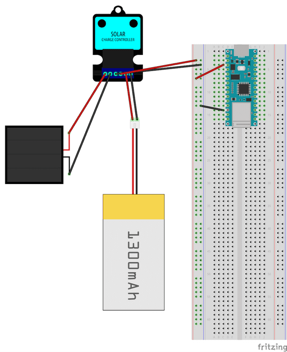
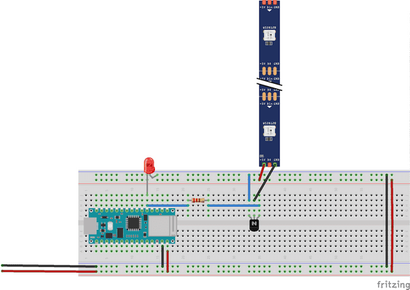
For this project, there are two circuits involved. Neither are particularly complex, but they work together wirelessly to complete my goal.
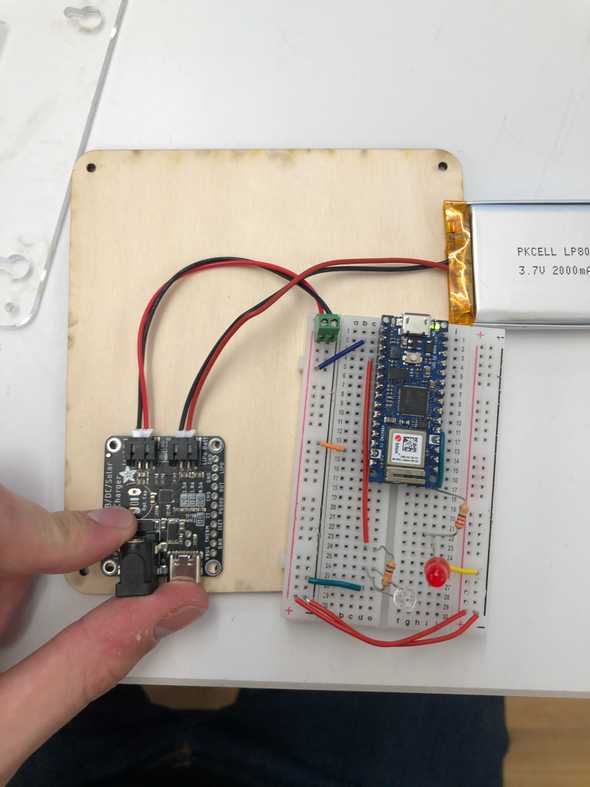
First is the solar circuit. It is simple. It uses an adafruit solar charger, a 1300mAh 3.7V battery, and a 6V .3A solar panel. The solar panel charges the battery, which in turn powers the Arduino.
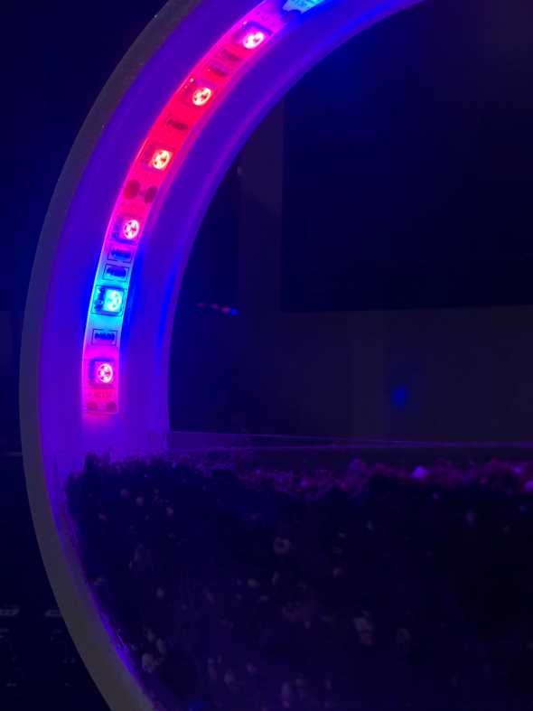
The second one receives the light data from the Arduino IoT Cloud, then uses a 12V power supply (plugged into Vin) to control a grow light LED strip. Using a transistor (TIP120), we are able to supply the current necessary to handle adjustment of brightness
Code
There is no real code for the wireless communications. By using Arduino IoT cloud, I am able to synchronize a variable (brightness), which can be accessed by either microcontroller. This allows me to process and write over the value as much as I please. In a later iteration, I would like to be able to do it independent of a web server (just bluetooth or IR or something).
Solar Charger Code:
#include "thingProperties.h"
#define ledPin 2
int analogVal = 0;

void setup() {
  // Initialize serial and wait for port to open:
  Serial.begin(9600);
  // This delay gives the chance to wait for a Serial Monitor without blocking if none is found
  delay(1500);

  // Defined in thingProperties.h
  initProperties();

  // Connect to Arduino IoT Cloud
  ArduinoCloud.begin(ArduinoIoTPreferredConnection);

  /*
     The following function allows you to obtain more information
     related to the state of network and IoT Cloud connection and errors
     the higher number the more granular information you’ll get.
     The default is 0 (only errors).
     Maximum is 4
  */
  setDebugMessageLevel(2);
  ArduinoCloud.printDebugInfo();
  pinMode(ledPin, OUTPUT);
}

void loop() {
  ArduinoCloud.update();

  analogVal = analogRead(A0);

  if (analogVal != 0){
    brightness = analogVal;
  };

  analogWrite(ledPin, analogVal);

  Serial.print("BRIGHTNESS: ");
  Serial.println(brightness);

  Serial.print("ANALOG: ");
  Serial.println(analogVal);
}

void onBrightnessChange() {
  // Do something

}
Grow Light Code:
Here you will notice some adjustments to the raw data. This is because, while I thought I had found a way to make a simple photoresistor give me the values I want, it turned out to be ultimately too noisy for the functions to work. I think ultimately, it will make more sense to use a UV sensor of sorts. It will be less range and more simple to map, but it will be less sensitive to the sunlight itself, as it can be sunny but low UV.
#include "thingProperties.h"
#define ledPin 2

int invert;
int adjusted;
int past = 0;

void setup() {
  // Initialize serial and wait for port to open:
  Serial.begin(9600);
  // This delay gives the chance to wait for a Serial Monitor without blocking if none is found
  delay(1500);

  // Defined in thingProperties.h
  initProperties();

  // Connect to Arduino IoT Cloud
  ArduinoCloud.begin(ArduinoIoTPreferredConnection);

  /*
     The following function allows you to obtain more information
     related to the state of network and IoT Cloud connection and errors
     the higher number the more granular information you’ll get.
     The default is 0 (only errors).
     Maximum is 4
 */
  setDebugMessageLevel(2);
  ArduinoCloud.printDebugInfo();
  pinMode(ledPin, OUTPUT);
}

void loop() {
  ArduinoCloud.update();
  // Your code here
  adjusted = map(brightness, 0, 300, 0, 255);
  if (adjusted < 200){
    adjusted -= 100;
  }
  invert = 255-adjusted;
  if (invert < 0){
    invert = 0;
  };
  if (invert > 255){
    invert = 255;
  };

  if (invert > past){
    past++;
  }
  if (invert <= past){
    past--;
  }
  if (past <= 0){
    past = 0;
  }
  Serial.println(past);
  analogWrite(ledPin, past);
  delay(10);
}

void onBrightnessChange() {
  // Do something

  // Serial.print("BRIGHTNESS: ");
  // Serial.println(brightness);
  // Serial.print("ADJUSTED: ");
  // Serial.println(adjusted);
  // Serial.print("INVERTED: ");
  // Serial.println(invert);
}
CAD
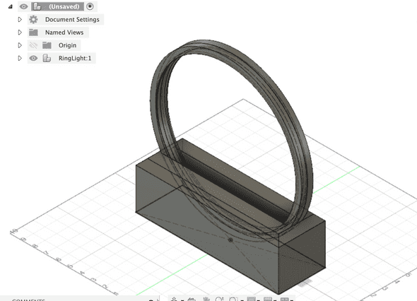
For this project, I used Fusion 360 to create a model that would be used for this whole project
Schematic Drawings
There are a lot of changes in the final project to this, but I think overall the changes make it more aesthetically sensible. So, I am going to use Fusion to eventually update the design.
There are essentially 3 grooves in this design. We have the outer ring, the first inner ring (to secure acrylic), then an innermost ring that recesses and houses the LED strip. Furthermore. There are 4 pin slots inside as well. These act as a way to align the two halves of the ring (because it will need to be CNC’d in 2 pieces on a 3-axis).
The base simply houses the ring securely, but I don’t love the recessed
Fabrication
Fabrication took a little bit of time here, I am not 100% confident in this process. However, the prototype here looks quite nice.
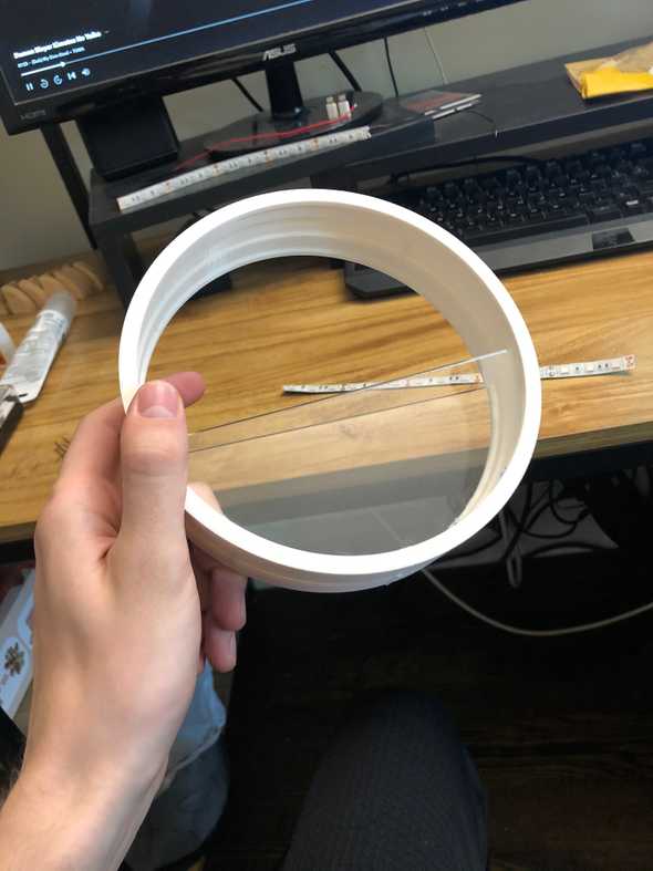
First, I decided to 3D print the rings. I had to reduce the size by 50%, but overall I am happy with my decision.
The first thing I had to do was drill the holes that were printed with a 1/16 drill bit. Due to the fidelity of the 3D print, they were unusable otherwise, but this plan worked great.
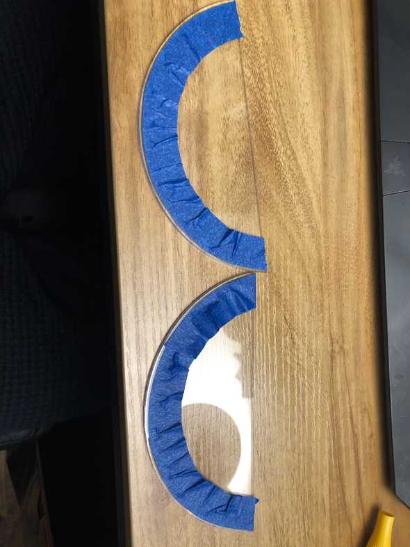
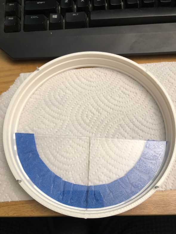
Next, I laser cut the Acrylic sides. After testing some adhesives, I discovered that super glue, then silicone grout would be the most secure and water-tight. So, I taped up the acrylic to stop any visible bleed into the acrylic.
I adhered the acrylic, then mounted the sides.
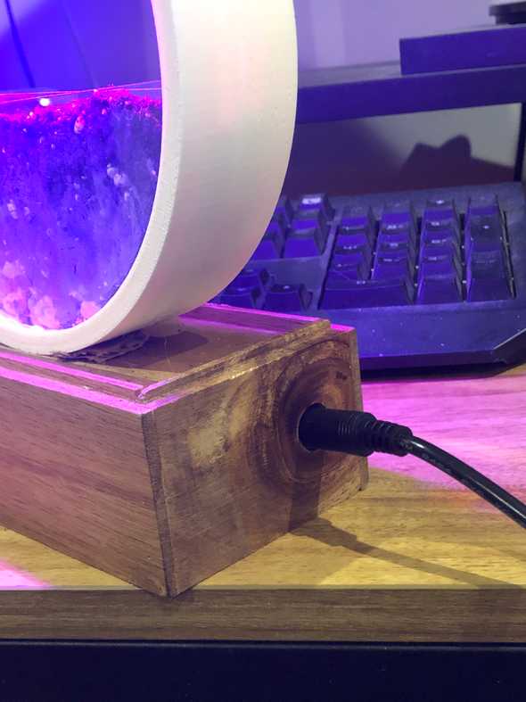
Next, I used a box from the container store as the base. I secured a bolt, the circuit, and the power supply within it then mounted the lights. After that, I was all finished!!
Update 3 (Week12): CAD Draft, Housing Solar Panel
Before I go into what I have done, I need to go through what I still need to do:
- Wireless communication between arduinos (Bluetooth? WiFi?)
- LED control using the light data
- Fabricate the piece.
The two main things I have done this week are build a housing for my solar circuit and draft the first iteration of the grow light enclosure. The housing is just about finished, but I am waiting for my standoffs to arrive in the mail. They should arrive tomorrow.

Then, I drafted the grow light. This will be done as a prototype build. I am finishing the CAD on it this week so it can be cut by a local shop and back in my hands ASAP.
This still has 3 more things to figure out:
- Widen the ring width to accomodate more soil
- How does the acrylic fit into the frame
- carve out area for arduino nano
Update 2 (Week11): Finished Solar Circuit
This week I was able to set up my solar circuit. The arduino can be powered for a long period of time with just about 2 hours of GOOD sunlight. The solar charger works, and I have set up a light sensor that works, but I need to find a new one.
This one isn’t sensitive enough. It will basically be at max with a little bit of light, and 0 with not too much light. As such, it is just going to give all or nothing to the LEDs, making it nearly impossible for this to work. I cannot currently find anything that will work, I have already reached out to my cohort’s discord.
I have photos of all of this, but I got dumped the other day and am emotionally exhausted. I promise I will update them here when I’m feeling a little better.
Update 1 (week10) : Slight Adjustments and Bill of Materials
For this first update for this project is that I want to take it in a different direction. I decided to talk to some of my friends who do not have windows. They loved the idea of having a small plant that blooms by opening and closing, but said they’d rather just have real plants.
I still want to make the piece with a sun-reactive plant, but in the interest of usability and time, I want to adjust it slightly. Nothing will be changing on the solar front, but I am going to use it to control a grow light instead. I would like to design the grow light housing so its quite nice and sleek, so it should still be nice looking.
Usually, you are not supposed to dim your grow lights, but you are also not supposed to keep them on all day. This piece will adjust the total light output (adjusted to be always at a useful level) based on the light outside.
Bill of Materials
I am sorry this is in flux, I have some questions about batteries and keeping the system safe.
Written by Philip Cadoux, current ITP student and Creative Technologist. Follow me on Instagram
