Physical Computing: Assignment 1
October 07, 2020
Winds of the Future
Final Documentation at bottom
Concept
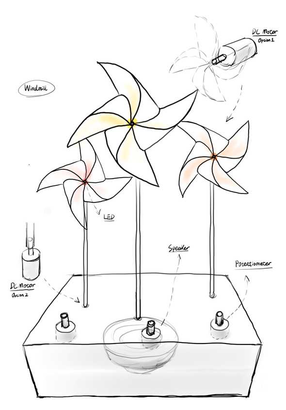
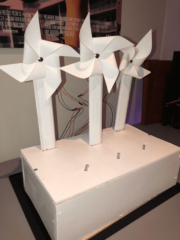
When we met, Bei and I were both interested in the idea of wind. We combined ideas and talked logistics and eventually settled on utilizing DC motors to spin pinwheels made out of paper. We felt that this would be both visually pleasing as well as capable of pushing us technically.
Originally, we also wanted to have each pinwheel output a lovely chime sound that would change pitch based on the speed of the pinwheel. We eventually had to edit this idea.
Circuit
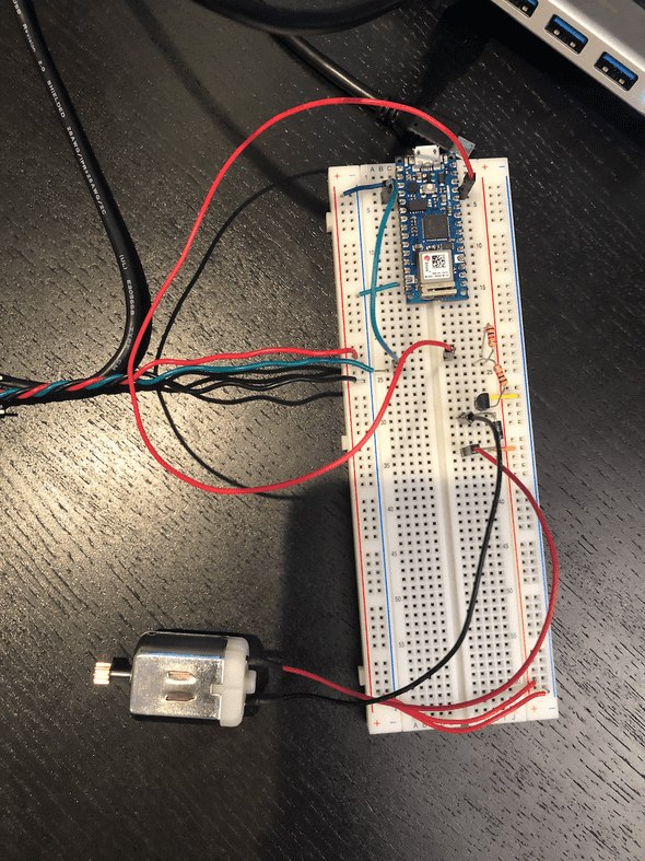
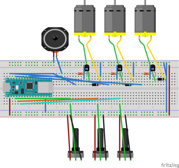
The circuit was actually one of the easier parts to this process. The main thing we had to learn how to use was a Transistor, a component capable of handling the flow of electric current in a way that allows a small amount of current in the “Base” to turn into a larger current in the other “collector” and “Emitter.” After seeing that, it wasn’t too difficult to wire up. Pictured below is our first iteration of the piece.
We had it hooked up to a single potentiometer (which had wires soldered and spun together). After that it was a matter of just scaling up. We were very nervous about voltage falloff (a term I am using here that probably doesn’t make sense), but we think the transistor helped to amplify the current and keep things moving. Quickly it got scaled up.
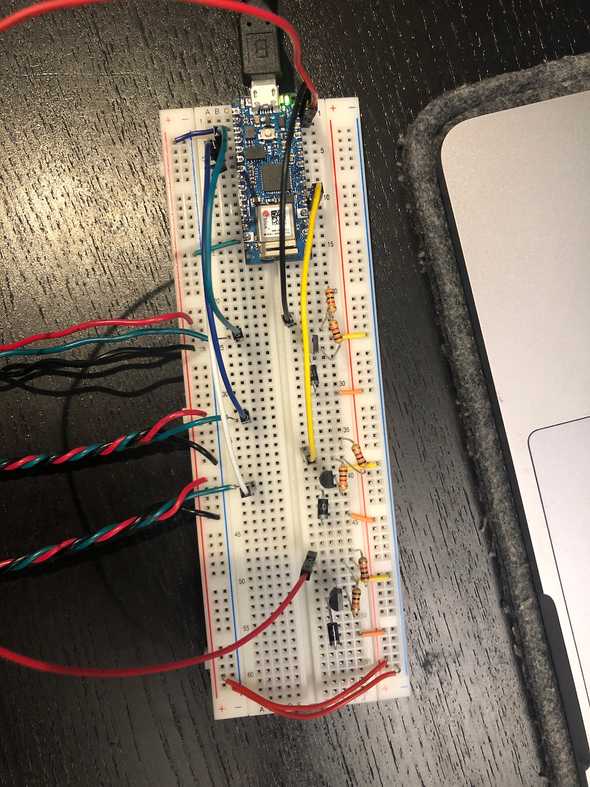
After that, we tried a prototype pinwheel and new everything was set up
Here is the final circuit (Adding the speaker w/o a resistor was a decision made for volume).
Code
First, we took stock of what needed to be defined:
#define potPinA A0
#define potPinB A1
#define potPinC A2
#define motorPinA 12
#define motorPinB 5
#define motorPinC 11
#define speakerPin 9
First, we started by going straight to the loop and writing pseudocode for what we needed to do (I am sorry to say I deleted it). Nevertheless, that helped us write the variables.
int potValueA = 0;
int potValueB = 0;
int potValueC = 0;
int motorValue = 0;

int topSpeed = 255;
int bottomSpeed = 100;
float averageFrequency;
That brings me to the loop for the motors. I think it is important to note that it is NOT necessary to have potValues ABC for this type of circuit. You could simply re-declare potValue as the program executes the loop. We ended up adding the differences when we began playing with sound.
potValueA = analogRead(potPinA);
motorValue = map(potValueA, 0, 1023, bottomSpeed, topSpeed);
analogWrite(motorPinA, motorValue);

potValueB = analogRead(potPinB);
motorValue = map(potValueB, 0, 1023, bottomSpeed+20, topSpeed); //Small power difference, added 20 to bottom speed to stop slowing down
analogWrite(motorPinB, motorValue);

potValueC = analogRead(potPinC);
motorValue = map(potValueC, 0, 1023, bottomSpeed, topSpeed);
analogWrite(motorPinC, motorValue);
Finally there was sound. We played with the Mozzi Library as well as a tutorial on audio synthesis using PWM, but truly could not figure anything out. Afterwards, we tried to use each potentiometer to output a frequency through the same speaker and it was absolutely awful. Frankly, removing sound entirely is the direction we went with as our options, but for the sake of this code - PotA controls a frequency. We also played with an average frequency, but it didn’t do much for us.
  float frequency = map(potValueA, 0, 1023, 1000, 5000);
  tone(speakerPin, frequency, 20);
//  float mappedFrequency = map(potValueA, 0, 1023, 1000, 8000);
//  float averageFrequency = mappedFrequency * 0.1 + averageFrequency * 0.9;
//  tone(speakerPin, averageFrequency, 10);
Here is all the code we have in our file:
#define potPinA A0
#define potPinB A1
#define potPinC A2
#define motorPinA 12
#define motorPinB 5
#define motorPinC 11
#define speakerPin 9

int potValueA = 0;
int potValueB = 0;
int potValueC = 0;
int motorValue = 0;

int topSpeed = 255;
int bottomSpeed = 100;
float averageFrequency;

void setup() {
  Serial.begin(9600);
}
void loop() {
  potValueA = analogRead(potPinA);
  motorValue = map(potValueA, 0, 1023, bottomSpeed, topSpeed);
  analogWrite(motorPinA, motorValue);

  potValueB = analogRead(potPinB);
  motorValue = map(potValueB, 0, 1023, bottomSpeed+20, topSpeed);
  analogWrite(motorPinB, motorValue);

  potValueC = analogRead(potPinC);
  motorValue = map(potValueC, 0, 1023, bottomSpeed, topSpeed);
  analogWrite(motorPinC, motorValue);


  float frequency = map(potValueA, 0, 1023, 1000, 5000);
  tone(speakerPin, frequency, 20);
//  float mappedFrequency = map(potValueA, 0, 1023, 1000, 8000);
//  float averageFrequency = mappedFrequency * 0.1 + averageFrequency * 0.9;
//  tone(speakerPin, averageFrequency, 10);
  /*Serial.print("PotValue = " );
  Serial.print(potValue);
  Serial.print("Motor Value = ");
  Serial.println(motorValue);*/
}
Fabrication (Cadoux)
Bei and I did our fabrications separately, but hers looks WAY better, so our final documentation is wit her piece. That said, here is my ~journey~
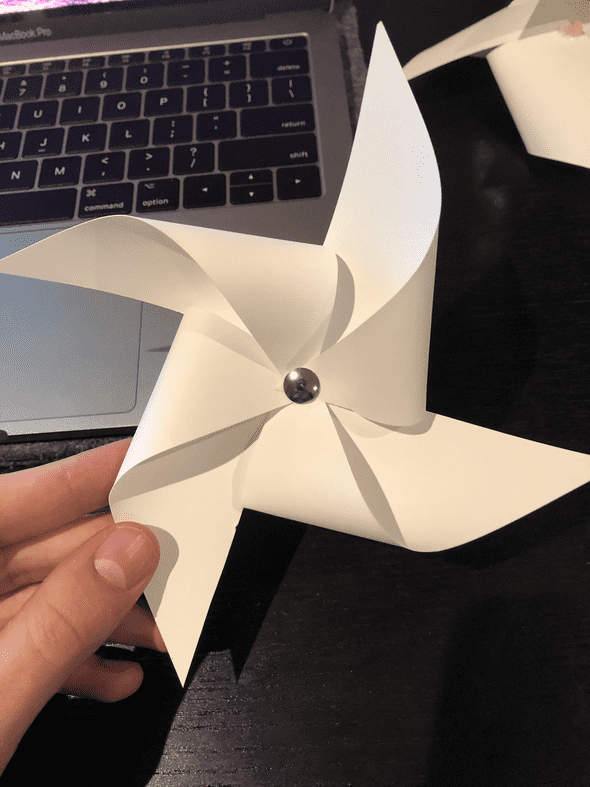
First, I had a feeling I needed to make my windmills smaller, so I did. They were very cute
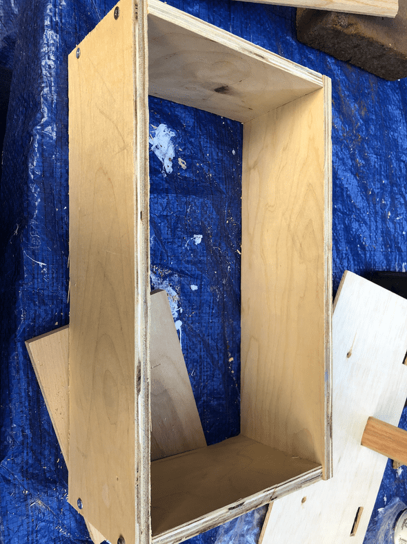
Afterwards, I went to the hardware store to buy a single, large piece of wood, but everything was too thick, so I asked someone and he was like “just tell me what you want and I’ll cut it for 15 bucks.” It was very embarrassing because I hadn’t thought far enough ahead and totally guessed on every measurement. I was pretty close on the enclosure, but ended up screwing myself on the parts to hold the motors (they were too thick to be effective).
Nonetheless, I took everything home and got to work.
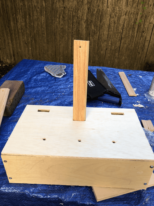
My top piece was 1/4 inch wood, so I was able to cut squares out of it (for the windmill stems) using my hobby knife, so that was quick and easy. Then, I held a few drillbits up to my potentiometer and found one that was reasonably thick and drilled holes. I used a second piece of wood underneath what I was drilling to A) not hurt my table and B) make a cleaner hole.
Next, I quickly read about how to drill a screw into wood (I quickly realized there was more to it then just drilling). I made my pilot holes and put together the walls of the enclosure.
Next was spray painting. I asked the guy for a matte white but he handed me a glossy white and I didn’t notice, so I just went with glossy. That wasn’t hard. Did it outside with my mask.
Last step was to drill the top onto the walls of the enclosure. I left the bottom unattached so I could easily access the circuit.
It was that moment that I realized I needed a spot to pull wires through, so I added a large hole in the back.
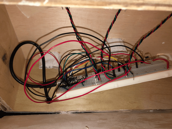
Here is the breadboard as it fits in the enclosure:
At this point I started to fail my documentation. I needed to use hot glue to secure the windmill stems because I didn’t have the right size wood or a way to effectively cut wood into a small enough piece to secure the stems.
The stems were also too thick, so I couldn’t easily get them to attach to my pinwheels, there was no easy way to connect them. Eventually I used hot glue, tape, and a dream. Eventually I got this:
Thoughts
I am very happy I spent the extra time to fabricate my own enclosure for this. I could have easily just used Bei’s, but the amount of mistakes I made set me up to be way better prepared for the next assignment.
I like our piece, but would love to learn more and take it further. I think it has the capacity to relax or leave some sort of zen in a person. Maybe I can revisit this at some point.
Final Documentation Video
Here is out final documentation for this assignment!
Written by Philip Cadoux, current ITP student and Creative Technologist. Follow me on Instagram
