Physical Computing: Week 01
September 13, 2020
Lab: Setting up a Breadboard
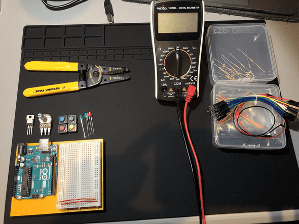
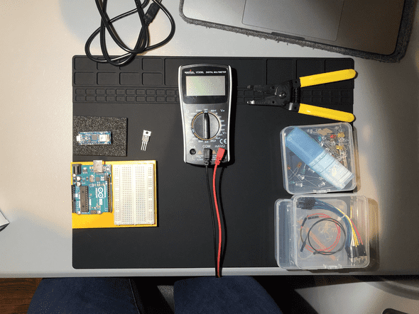
Things you’ll need:
I know that this lab called for a DC power supply and Jack, with a 5V voltage regulator. For most of these Labs, I swapped between the Arduino UNO and Arduino Nano 33IoT as the power source.
Will It Light?:
I was able to properly identify whether they all worked. I wasn’t confident that I could, but viewing as a circle with power and ground helped me a lot. I admit, I did not re-create the circuits, but there were many circuits in the other labs.
Lab: Electronics
Things you’ll need:
Testing the Meter:
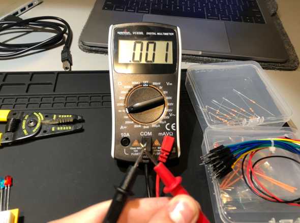
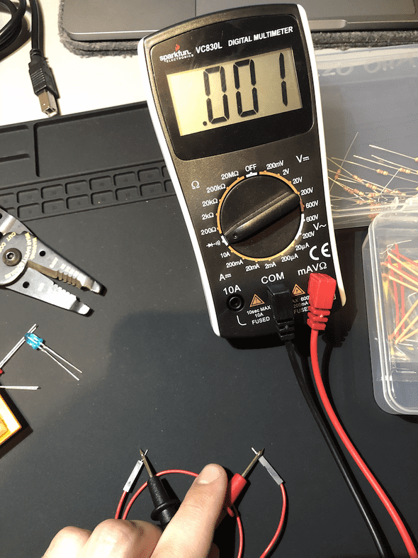
I have to admit, taking pictures of testing the meter, is not an easy feat. Firstly, I followed the directions to discover whether my Meter was functioning properly. Luckily, mine was new and functioned perfectly ( < 0.1 ):
Measuring Continuity
Touching 2 Ends of a Wire:
I used one of the wires that already had header pins and touched each end to it. It beeped immediately
Touching Two Points on a Switch:
Unfortunately, I could not find an effective way to take a photo of this specific exercise. What I did notice, is that on the 4 prongs of the switch, it was continuous across the prongs, but not parallel. So, when measuring continuity, unless the switch is pressed in, there is no connection between each side of the switch.
Probing Points on a Breadboard:
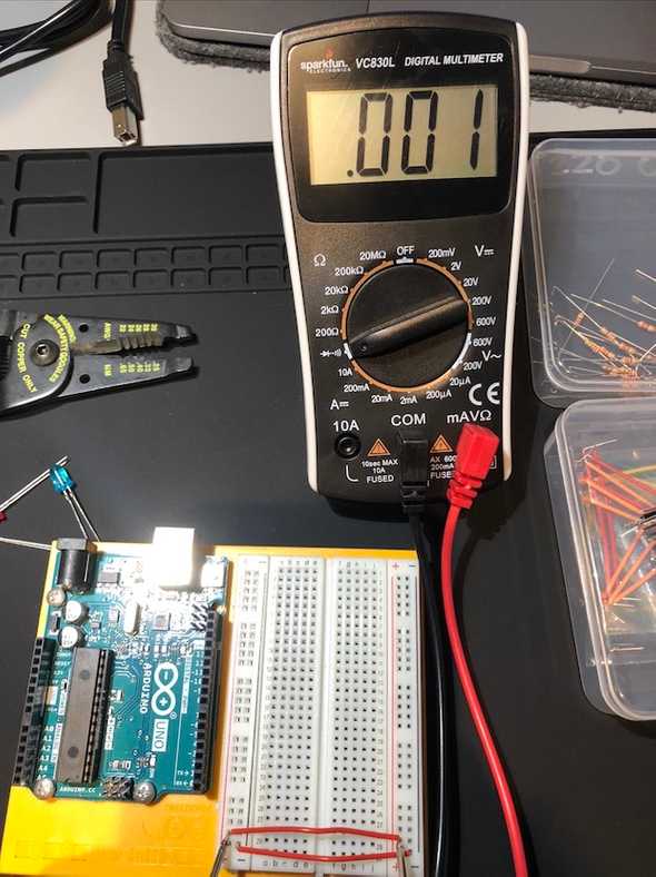 As I go back and begin to blog this, I realize that I sort of did this wrong. My jacks would not reach inside of the breadboard, so I added a wire that spanned the breadboard. So, when I measured continuity, I was just measuring the continuity of that wire, not the breadboard. However, by the time I completed these labs, I understood how the breadboard is connected.
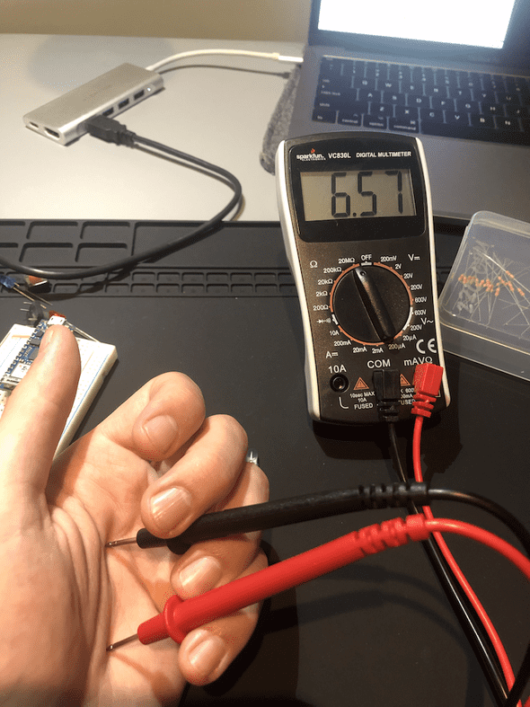
Measuring Continuity Across your Hand:
I also struggled a lot with taking a photo of this one. i was not able get continuity through my hand. I suppose the resistance was too high for anything to pass through it continuously.
Setting up the Breadboard:
Initially, I tried to set this up with the Arduino Nano, but I was too delicate and could not bring myself to push the nano into the breadboard. Eventually I did, but for the time being, I used the UNO.
Measuring Resistance of a Component:
Resistance of Resistor:
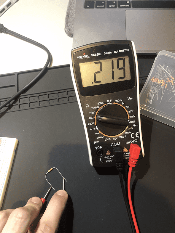
Here the resistance turned out to be 219 Ohms, which makes sense because I used a 220 Ohm resistor. The multimeter reads .219 because it is set for measuring up to to 2 kOhm.
Resistance and Diodes:
I couldn’t get a clean photo of this, but I did notice how it would flash a number before going to 0.
Resistance across your Hand:
This doesn’t surprise me very much. Having a ton of resistance checks out, otherwise I could probably find a way to shoot electricity out of my fingertips.
Measuring Voltage:
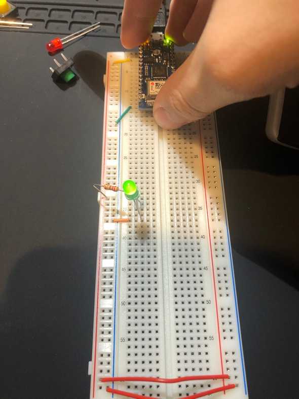
Firstly, here is the circuit I will be using for this exercise:
Unfortunately, this is where I was too nervous to push in the pins, so I switched it to be by powered by the UNO, which you will see in the following pictures.
Voltage across Power and Ground:
I couldn’t manage to take a photo of this. But I did see that the Voltage across the “whole circuit” was 5V.
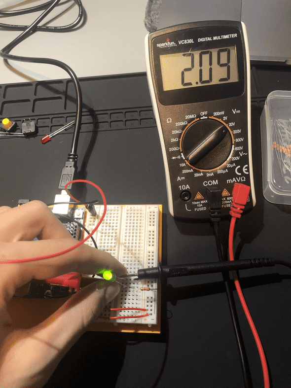
Voltage Drop across LED:
I did not get a negative Voltage here, but I got approximately 2V, which means the LED was using 2V/5V to power itself.
A switched LED Circuit
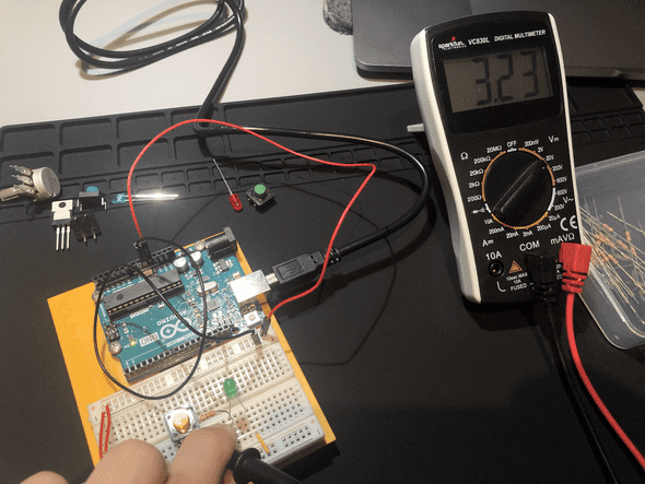
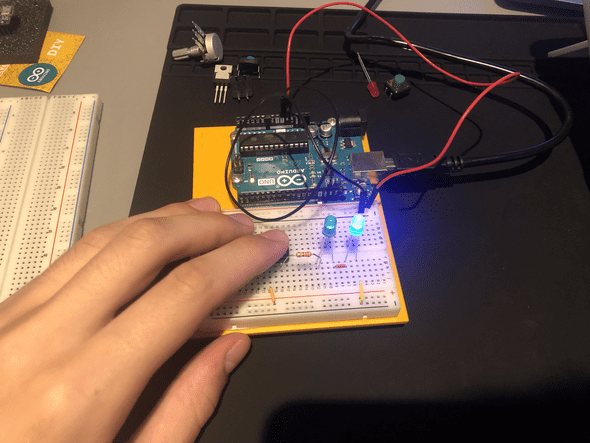
Here is the switched LED Circuit I made with the Arduino UNO as the power supply:
Adding up Voltage
I am honestly baffled that I was able to get this image at all. In the off position, the pushbutton utilizes considerable voltage, but the moment the button is pressed, it becomes akin to a wire and allows everything to pass through
Components in Series
Here is a switch with 2 LEDs in series:
The voltage across the resistor and 2 LED’s approximately reaches that of the total Voltage (perhaps just a smidge off). The rest is likely lost in heat.
Adding a third LED
This makes it so that the LED’s will not light up. It appears as though each LED requires around 2V to operate, 2*3 = 6, which is too much required energy for the circuit to work.
Components in Parallel/Measuring Amperage:
Here is a switch with 3 LEDs in Parallel:
As suggested, the voltage across the LEDs is exactly the same (give or take human error).
Unfortunately, I was not able to put the multimeter in series and take a photo, but I was able to confirm the information in the Lab.
Generating a Variable Voltage with a Potentiometer
Firstly, I had not yet watched the soldering tutorial, nor did it make sense for me to solder at the moment I was doing this lab. Instead, I used alligator clips to successfully use the Pot.
One thing I noticed about this specific exercise is that my potentiometer didn’t work exactly the same way as it is described. I had a bell-curve version where either extreme was the brightest and the middle was 0. Did I do something wrong?
Lab: Switches and PushButtons
Creative Switch
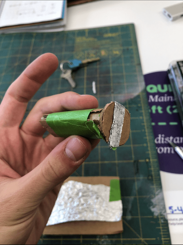
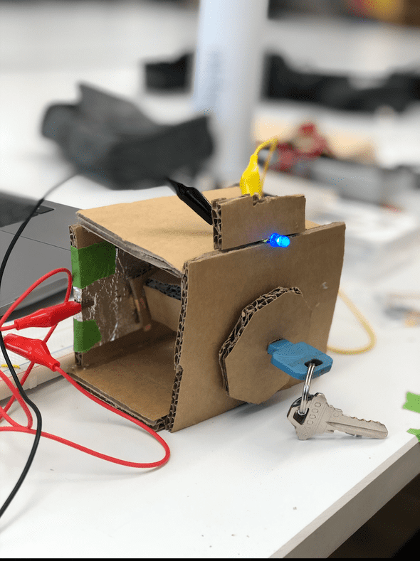
For this I decided to make Turnkey switch. I figured it would be a fun experiment to make something where turning a dial would activate a light.
So, I first had to figure out how to finish a circuit with a turning device.
First, I made a small cardboard cylinder with a strip of tinfoil around it.
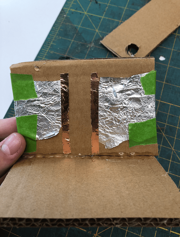
Next, I made a cardboard piece that had 2 pieces of tinfoil that were not connected (the turnkey would connect them)
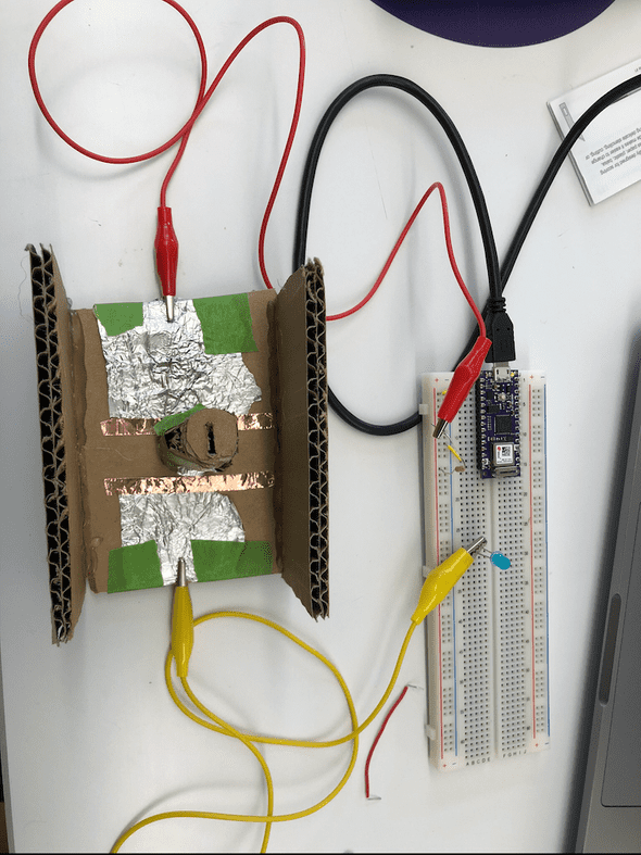
Third, I completed the circuit using aligator clips to handle the distance from the breadboard.
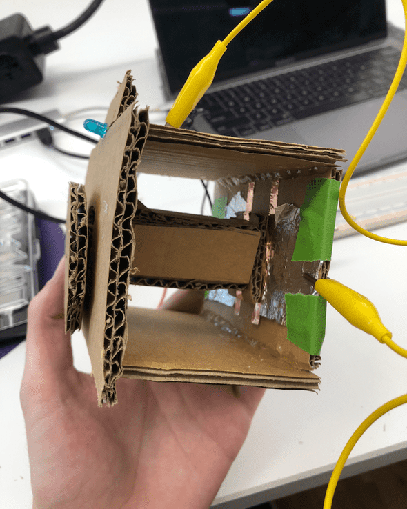
Then, I upgraded some of the parts (including the initial turnkey) and hot glued it into an enclosure. The “device” worked by using a conductive material to bridge the gap between the wires. The enclosure looked like this from the side:
And this from the front:
Arrangement of Switches
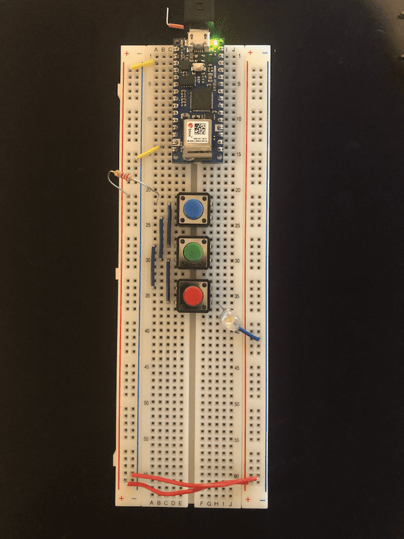
Three Switches in Parallel
This switch worked when any one of the buttons was pressed.
Three Switches in Series
This switch worked ONLY when all 3 switches were pressed.
Switching A Motor
I used a DC motor that I had laying around for this, but noticed that only a Servo was on the part list. I was going to use the Servo, but it appears that it requires programming in the arduino to function?
Dual Pole Switch
Completed switch:
Written by Philip Cadoux, current ITP student and Creative Technologist. Follow me on Instagram
